
White Paper
Overcoming the Bottlenecks of Shear Flow: A Modern Solution for High-Throughput Assays

Introduction
Shear stressThe tangential force per unit area from flowing fluid; a key parameter in vascular biology, platelet function, leukocyte rolling, and biofilm adhesion studies. plays a critical role in regulating biological processes such as cell-cell interactions, polarization,
permeability, and metabolism. However, many in vitro assays such as those used to study leukocyte adhesion,
platelet aggregation, or biofilmA structured microbial community attached to a surface, typically more tolerant to antibiotics/biocides than planktonic cells. formation are traditionally conducted in static systems like well plates or culture dishes, which fail to replicate the dynamic conditions found in vivo. To improve physiological relevance, researchers have increasingly adopted flow-based platforms, including parallel-plate flow chambers and platform rockers, which simulate in vivo environments by introducing shear stress through controlled fluid movement.
While these systems represent a step forward, they often suffer from limitations such as limited shear flowFluid movement that applies force to cells and biofilms; used to mimic physiological/pathological conditions. control, low throughput, and variability in results. These shortcomings can compromise data quality and reproducibility, leading to delays, increased costs, and reduced confidence in experimental outcomes. As such, there is a clear need for a high-throughput, reliable, and reproducible shear flow system that meets the growing demand for physiologically relevant data.
The Role of Shear Flow in Cellular Physiology
Circulating cells including endothelial cells¹, erythrocytes², platelets³, and leukocytes4 respond dynamically to
physiological shearFlow conditions intended to resemble those in vivo (e.g., vasculature, catheters, mucosal surfaces). stress. For example, shear stress as low as 7 dyn/cm² can alter the transcriptional profile of
epithelial cells⁵, and in leukocytes, it helps maintain their spherical shape for capillary transit⁴. Shear flow is also
commonly used in hematology assays to induce platelet activation without non-physiological agonists, which can
otherwise interfere with thrombin generation⁶.
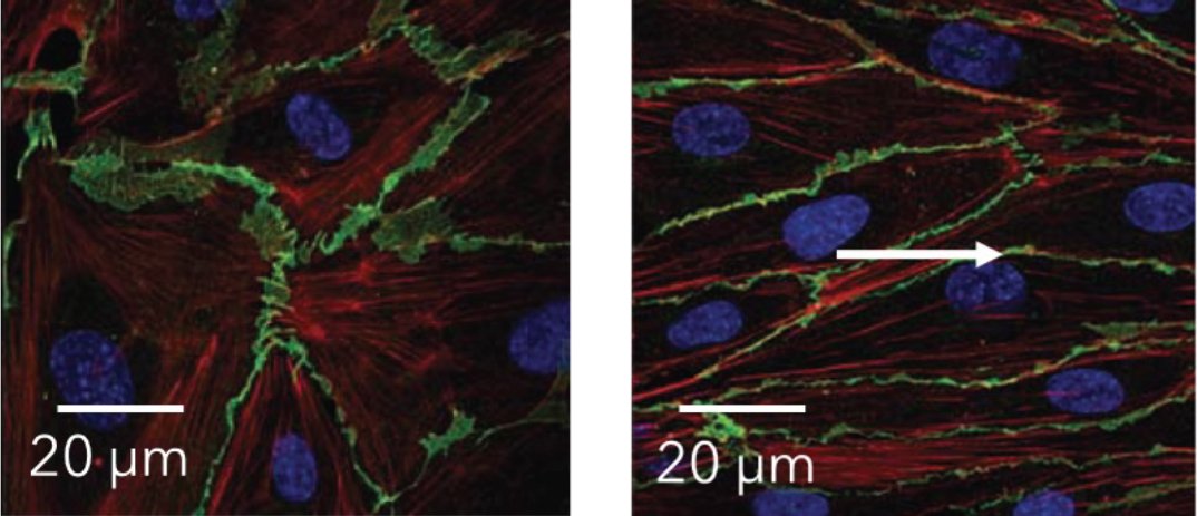
Figure 1. Human aortic endothelial cells (HAEC) with and without shear flow. Confocal microscopy images of HAEC monolayers under static (left) and 20 dyn/cm2 shear flow for 24 hours. Blue stain shows Hoechst-stained nuclei, red stain shows phalloidin-stained F-actin, and green stain shows VE-cadherinspecific antibody-stained cell membrane. The white arrow indicates the direction of flow. Adapted from Makwana et al. doi: 10.1177/026119291704500407
Beyond mammalian cells, shear stress significantly impacts non-eukaryotic organisms. It has been shown to enhance binding strength and biofilm formation in microbes such as Candida albicans⁷ and Escherichia coli⁸ (Figure 2). Continuous shear promotes nutrient delivery and waste removal across biofilm layers, altering biofilm architecture and antimicrobial resistance⁹,¹⁰. Together, these findings underscore the broad and critical influence of shear stress across diverse biological systems.
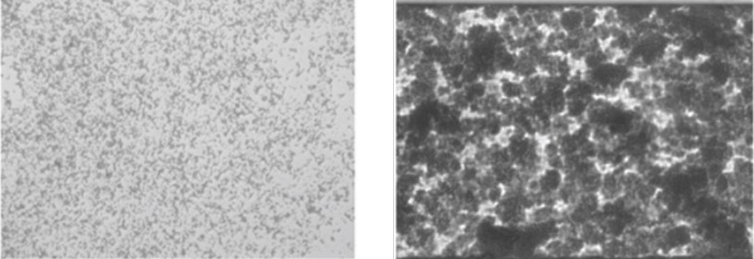
Figure 2. Biofilm formation with and without shear flow. Biofilm formation by E. coli strain EAEC 17.2 under static (left) and 1.0 dyn/cm² shear flow. Biofilms were stained with crystal violet. Adapted from Tremblay et al. 10.1128/AEM.04208-14
Limitations of Conventional Shear Flow Systems
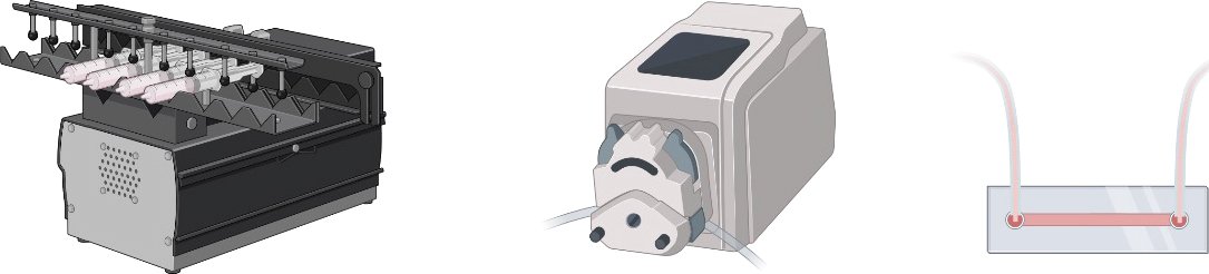
Shear flow remains underutilized despite its clear biological relevance. A major barrier is the lack of accessible, high-performance systems capable of delivering controlled conditions. Existing tools ranging from simple platform rockers to more complex parallel plate flow chambers (PPFCs) present significant limitations that restrict adoption.
Platform rockers offer a low-cost method to generate wall shear stress through fluid movement. However, these
systems lack the precision required for quantitative studies. Rocker-induced flow is inherently oscillatory, with little to no user control over speed, direction, or pulsatile flow profiles.
Parallel plate flow chambers (PPFCs) offer greater control over shear flow compared to simpler systems and are commonly used in both DIY and commercial formats. However, DIY PPFCs are complex and time-consuming to fabricate, and typically support only one sample at a time, limiting throughput. Shear stress uniformity is also a concern, with variability across the channel reaching up to 80%12. In addition, PPFCs, especially custom-built versions, require rigorous validation to ensure consistent and reproducible results11. While commercial systems help address some of these limitations, they present new challenges. The wide variety of tubing, flow chambers, and pump configurations can make setup cumbersome and error-prone. Regardless of format, all PPFCs require external pumps connected via tubing, which must be manually assembled and sterilized between experiments—introducing biosafety risks, increasing hands-on time, and reducing overall efficiency.
Push-and-pull syringe pumps are commonly used in both DIY and commercial PPFC setups to precisely control fluid flow. They allow fine-tuned regulation of flow rate, volume, timing, and direction, including unidirectional, bidirectional, and pulsatile flow profiles, making them suitable for replicating physiological shear conditions. However, throughput remains limited by the one-to-one relationship between each syringe and its corresponding PPFC. Although newer models can accommodate up to four syringes, all connected chambers receive identical flow rates, restricting experimental flexibility. Scaling up requires additional pumps, chambers, and syringes, significantly increasing cost, complexity, and bench space. High-end models can exceed $25,000 while still supporting only 1–4 samples.
Syringe pump-based systems also require careful hardware integration. Accurate shear stress delivery depends on precise selection and matching of tubing, Luer fittings, and filters, user-calculated flow rates based on fluid viscosity and chamber geometry. Filters also stand the risk of clogging when used with viscous fluids like blood or microbial suspensions, producing flow rate fluctuations that can induce Taylor dispersion13, compromising uniformity. Regular calibration and maintenance are essential to ensure consistent performance and leak prevention, further increasing the operational burden.
Peristaltic pumps offer a low-cost, simple option for generating shear flow. Fluid flow is driven by the compression of tubing with rollers, which disrupt laminar conditions, reduce shear stress precision and disrupt microscopic imaging. Dampeners are used to reduce these effects, but they add cost and complexity while insufficiently eliminating these problems. In addition, the pulse amplitude of peristaltic pumps does not replicate physiological rhythms like the heartbeat and can exert mechanical stress on cells, compromising assay accuracy.
As with syringe pumps, PPFCs using peristaltic systems require careful tubing selection, flow rate calculations, and typically support only one sample per setup. Despite their affordability, mechanical stress and the lack of control over the pulses generated by the pumps present significant limitations for experiments demanding precise shear delivery and high cell viability.
A Modern Approach to Shear Flow Systems
BioFlux systems are designed to be complete, high-throughput, low-maintenance shear flow systems that use
microfluidic technology to overcome the challenges presented by current methods. Compared to PPFCs or rockers, BioFlux systems have a more extensive dynamic range of laminar flow and enhanced field uniformity. User-defined shear flow delivery rates are computer-controlled, eliminating time-consuming calculations and calibrations.
Typical BioFlux Workflow
The features of BioFlux Shear Flow Systems (Table 1) can provide benefits to a vast array of investigations,
including assays of biofilms, cellular adhesion, thrombosis, disease modeling, and more. Although the reagents and experimental objectives of these assays can vary greatly, most assays conducted using a BioFlux system follow similar procedures (Figure 4).
Table 1
| Feature | Platform Rocker | Syringe Pump | Peristaltic Pump | BioFlux |
|---|---|---|---|---|
| Mimic in vivo shear stress | ||||
| Multi-sample throughput | ||||
| Simultaneously image multiple samples | ||||
| Multiple types of shear flow (bidirectional, pulsatile, oscillatory) | ||||
| Requires flow chamber assembly | ||||
| Requires pre-experiment calibration | ||||
| Requires tubing for fluid | ||||
| Rapid compound addition/switching |

System Design and Operation
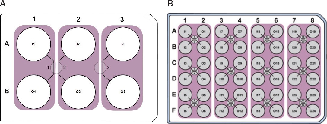
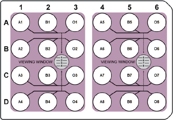
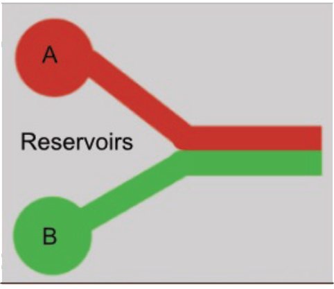
BioFlux operation is based on leveraging the advantages of microfluidics for precise flow control. Using a proprietary design, networks of laminar flow cells are integrated onto the bottom of Society for Biomolecular Sciences (SBS) standard-sized 6, 24, and 48-well plates. The embedded microfluidic channels on 6 and 48-well BioFlux plates connect horizontal well pairs into independent flow chambers (Figure 5), enabling 3 and 24 independent experiments, respectively. BioFlux 24-well plates support 8 experiments per plate (Figure 6) and provide enhanced experimental flexibility by connecting two inlet wells to a single outlet, enabling rapid compound compound/reagent switching or the creation of a liquid gradient using two flow streams (Figure 7).
Reagents are added to the wells of the plates using conventional means (e.g., pipettes, syringes, liquid handlers). A plate interface is attached to the plate to deliver controlled air pressure generated by the BioFlux Control software to individual wells. As air flows into the wells, reagents are driven into the connected microfluidic channels embedded within the plate and then into the adjacent well (Figure 8). The use of air to drive fluid through the channel eliminates liquid contact with tubing, drastically reducing biosafety risk, cleaning time, and consumable costs.
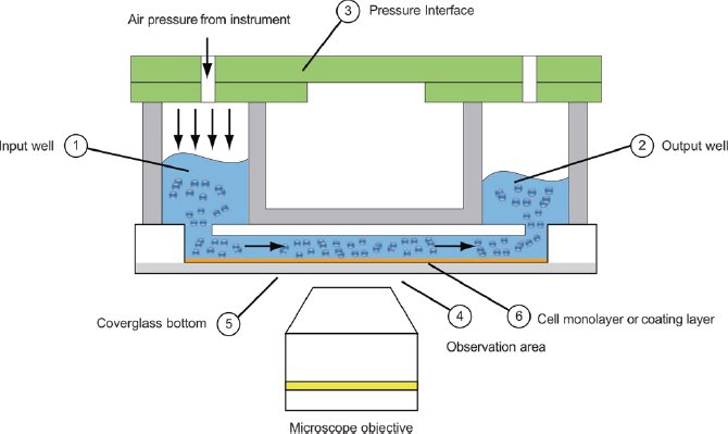
Figure 8. BioFlux Operation. When attached to a BioFlux plate, the interface delivers air pressure to drive fluid flow from an inlet well, across the viewing window where microscopy can be performed, and into an outlet well. Flow direction is user-defined and can be unidirectional or bidirectional.
BioFlux Plates Characteristics
The upper portion of BioFlux plate wells is constructed from clear polystyrene, while the microfluidic channels are
molded from polydimethylsiloxane (PDMS) and have dimensions specifically designed to achieve the desired wall shear stresses. The channel bottoms are made from 170 μm coverslip-grade glass, providing optimal imaging quality for brightfield, fluorescence, and confocal microscopy (Figure 9).
All BioFlux plates are individually sterile packaged and go through rigorous quality control to ensure functionality and consistency.
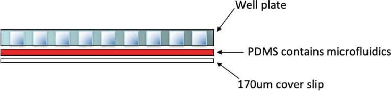
Figure 9. Configuration of the viewing window of a standard BioFlux plate. The microscope viewing window is constructed of microfluidic channels embedded into a layer of PDMS that is sandwiched between a standard polystyrene microplate and 170 μm cover slip glass.
Table 2: BioFlux Plate Characteristics
| Plate | 48-well (Low Shear) | 48-well (High Shear) | 24-well (Low Shear) | 6-well |
|---|---|---|---|---|
| Wall Shear Stress (dyn/cm²) | 0-20 | 0-200 | 0-20 | 0-60 |
| Channel height, non-viewing regions (mm) | 0.07 | 0.075 | 0.075 | 0.1 |
| Channel height, viewing region (mm) | 0.07 | 0.075 | 0.075 | 0.05 |
| Channel length, viewing region (mm) | 4 | 8 | 8 | 7.5 |
| Channel width, viewing region (mm) | 0.35 | 0.25 | 0.35 | 0.37 |
| Channel length, inlet to viewing region (mm) | 210 | 7.3 | 90 | 411.5 |
| Channel width, inlet to viewing region (mm) | 0.9 | 0.43 | 0.6 | 0.1 |
| Channel length, viewing to outlet (mm) | 9.6 | 46.3 | 28.9 | 34.5 |
| Channel width, viewing to outlet (mm) | 0.35 | 0.15 | 0.27 | 0.2 |
Controller & Interface
The BioFlux controller contains dual air compressors and electropneumatic regulators that enable the delivery of controlled air pressure to drive user-defined fluid flow with precision. During standard operation, ambient air is passed through multiple filters to filter out particles down to 0.01 μm. Air pressure is then delivered by an array of tubing that connects the BioFlux controller with the plate interface, which attaches to the top of a BioFlux plate and acts as a pressure distribution manifold. Air pressure driven flow provides the BioFlux with the unique advantage of having all experimental samples and reagents contained within the plate. The BioFlux plate interface, tubing, and controller do not encounter any liquids, eliminating the need to clean or regularly replace tubing.

Microenvironmental Control
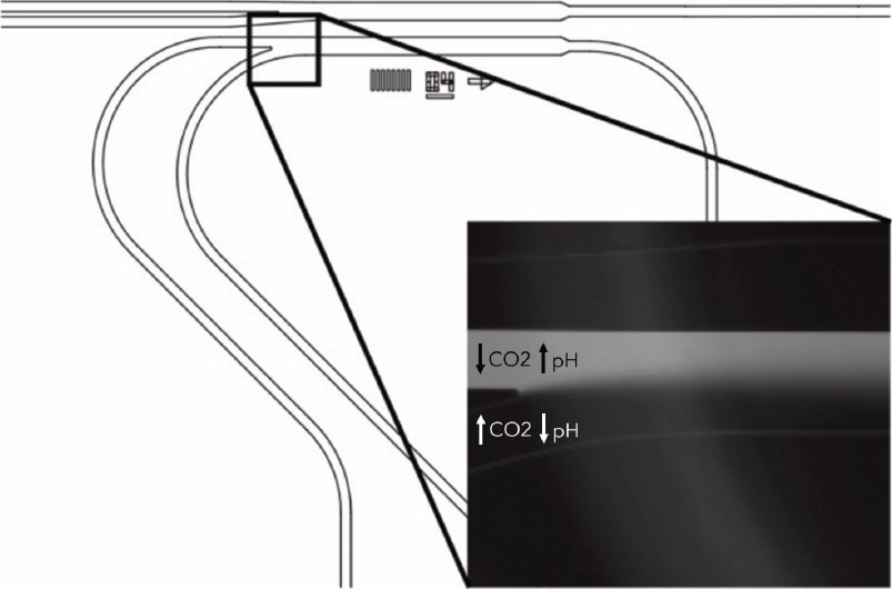
In addition to enabling physiologically relevant shear flow assays, BioFlux Shear Flow systems offer environmental control features to emulate in vivo conditions. A plate heater adapter maintains temperature during live cell imaging, while gas ports support connections to external gas sources for regulation of gas composition. This enables experiments under varied conditions, such as hypoxia or physiological oxygen. The unique design of BioFlux 24-well plates also supports the creation of dual gas gradients within a single channel, facilitating studies of cell behavior across pH or oxygen gradients (Figure 10). For extended culture under flow, the tubing connecting the controller to the interface can be routed into a standard incubator, allowing continuous shear application under stable environmental conditions.
BioFlux Control Software
BioFlux Control Software serves as the primary user interface to control the operation of the microfluidic
channels. The software enables control of active microfluidic channels on the plate, set precise wall shear
stresses using 0.01 dyn/ cm2 increments, and set flow direction and source. User-defined protocols consisting
of flow type (unidirectional, bi-directional, or pulsatile), run time, and wall shear stress can be saved and easily recalled for repeated experiments.
Conclusions
As the scientific community demands more physiologically relevant in vitro models, the limitations of traditional shear flow systems—low throughput, inconsistent flow control, and complex setup—have become increasingly apparent. BioFlux Shear Flow Systems offer a transformative solution, combining microfluidic precision, automation, and scalability to overcome these longstanding bottlenecks. By eliminating the need for external pumps and complex tubing, minimizing biosafety risks, and enabling flexible, programmable shear flow protocols, BioFlux empowers researchers to generate high-quality data with ease.
From leukocyte adhesion and platelet aggregation to biofilm formation and cancer cell migration, BioFlux supports a wide range of assays across disciplines— delivering reliable performance for both routine and advanced studies. As biological research continues to evolve, BioFlux stands ready to meet the challenge, enabling deeper insights into cellular behavior under flow and unlocking new opportunities for discovery.
References
Makwana, O., Flockton, H., Watters, G. P., Nisar, R., Smith, G. A., Fields, W., & Bombick, B. (2017). Human aortic endothelial cells respond to shear flow in well-plate microfluidic devices. Alternatives to laboratory animals : ATLA, 45(4), 177–190.
https://doi.org/10.1177/026119291704500407Johnson R. M. (1994). Membrane stress increases cation permeability in red cells. Biophysical journal, 67(5), 1876–1881. https://doi.org/10.1016/S0006-3495(94)80669-1
Kroll, M. H., Hellums, J. D., McIntire, L. V., Schafer, A. I., & Moake, J. L. (1996). Platelets and shear stress. Blood, 88(5), 1525–1541.
Moazzam, F., DeLano, F. A., Zweifach, B. W., & Schmid-Schönbein, G. W. (1997). The leukocyte response to fluid stress. Proceedings of the National Academy of Sciences of the United States of America, 94(10), 5338–5343.
https://doi.org/10.1073/pnas.94.10.5338Flitney, E.W., Kuczmarski, E.R., Adam, S.A. and Goldman, R.D. (2009), Insights into the mechanical properties of epithelial cells: the effects of shear stress on the assembly and remodeling of keratin intermediate filaments. The FASEB Journal, 23: 2110-2119. https://doi.org/10.1096/fj.08-124453
Roka-Moiia, Y., Walk, R., Palomares, D. E., Ammann, K. R., Dimasi, A., Italiano, J. E., Sheriff, J., Bluestein, D., & Slepian, M. J. (2020). Platelet Activation via Shear Stress Exposure Induces a Differing Pattern of Biomarkers of Activation versus Biochemical Agonists. Thrombosis and haemostasis, 120(5), 776–792.
https://doi.org/10.1055/s-0040-1709524Chan CXJ, Lipke PN.2014.Role of Force-Sensitive Amyloid-Like Interactions in Fungal Catch Bonding and Biofilms. Eukaryot Cell13:.
https://doi.org/10.1128/ec.00068-14Tremblay, Y. D., Vogeleer, P., Jacques, M., & Harel, J. (2015). High-throughput microfluidic method to study biofilm formation and host-pathogen interactions in pathogenic Escherichia coli. Applied and environmental microbiology, 81(8), 2827–2840.
https://doi.org/10.1128/AEM.04208-14S. Wäsche, H. Horn, D.C. Hempel; Mass transfer phenomena in biofilm systems. Water Sci Technol 1 February 2000; 41 (4-5): 357–360. doi: https://doi.org/10.2166/wst.2000.0466
P. Ramasamy, X. Zhang; Effects of shear stress on the secretion of extracellular polymeric substances in biofilms. Water Sci Technol 1 October 2005; 52 (7): 217–223. doi:
https://doi.org/10.2166/wst.2005.0204Heydorn, A., Ersbøll, B. K., Hentzer, M., Parsek, M. R., Givskov, M., & Molin, S. (2000). Experimental reproducibility in flow-chamber biofilms. Microbiology (Reading, England), 146 ( Pt 10), 2409–2415. https://doi.org/10.1099/00221287-146-10-2409
B.J Chung, A.M Robertson, D.G Peters. (2003). The numerical design of a parallel plate flow chamber for investigation of endothelial cell response to shear stress. Computers & Structures, 81, Issues 8–11: 535-546.
https://doi.org/10.1016/S0045-7949(02)00416-9.